Deleted
Deleted Member
Member since January 1970
Posts: 0
|
Post by Deleted on Jan 15, 2017 20:01:16 GMT -5
I just love enterprise and encouraging new entrepreneurs. It's the sales manager in me! uL stuff is easily avoided. The trick is to sell the unit without power cord attached. The customer finished assembly. Plus UL isn't required. And the workaround for SsDI is he doesn't make any money personally. SSDI can't stop you from sharing.  ziggy ziggy |
|
ziggy
spending too much on rocks

Member since June 2016
Posts: 483 
|
Post by ziggy on Jan 15, 2017 20:17:12 GMT -5
I just love enterprise and encouraging new entrepreneurs. It's the sales manager in me! uL stuff is easily avoided. The trick is to sell the unit without power cord attached. The customer finished assembly. Plus UL isn't required. And the workaround for SsDI is he doesn't make any money personally. SSDI can't stop you from sharing. ziggy Points well made and considered. But there is this one part "We just don't have the energy (not to mention money) that it would all take. Hubby is literally living on borrowed time and was looking forward to relaxing in his retirement (read as "picking up rocks") and not trying to start up a new product. I made a mistake when I mentioned we might try and market it. I didn't tell him first." He's right. He worked all his life and needs a break. |
|
Deleted
Deleted Member
Member since January 1970
Posts: 0
|
Post by Deleted on Jan 15, 2017 20:18:18 GMT -5
Best wishes in retirement! ziggy |
|
ziggy
spending too much on rocks
Member since June 2016
Posts: 483
|
Post by ziggy on Jan 15, 2017 20:25:11 GMT -5
Best wishes in retirement! ziggy Yep, thanks. No more getting up everyday before the sun. Sleeping in when you want. Actually having the time to really watch a sunset together. Going fishing and rockhounding when the whim hits. That's what he worked all those years for. But he still likes to tinker and build things. |
|
ziggy
spending too much on rocks
Member since June 2016
Posts: 483
|
Post by ziggy on Jan 16, 2017 15:10:17 GMT -5
The build progresses today. Hubby started by measuring and scribing lines with a carbide tipped scribe. Here he scribes a cut line and the saw blade width kerf line. He really started out first by squaring up his saw clamp to saw blade. The piece he is working on will be the three sided frame that the pan sits in.  Into the chop saw it goes for the first of four cuts. 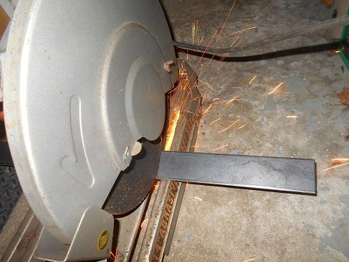 The big piece was too long so it needed cut twice accounting for the 4 cuts I mentioned. 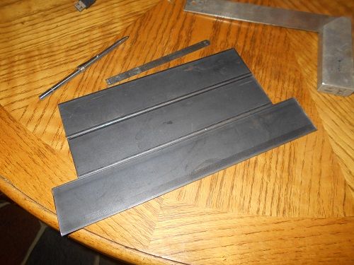 Next he cuts a 4 inch piece of angle steel x 2. He increased the length of the feet because he is thinking about using 2 stainless steel C-clamps to hold the depth stop strip in place. With space under the pan he can now just C-clamp the depth stop strip right to the bottom of the pan.  The saw is cutting well today. 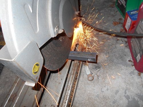 After measuring and scribing guidelines for hole location Hubby center punches where the drill needs to go. 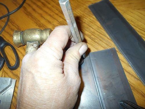 The punch marks.  Out in the pole barn we have a nice drill press to get good easy holes. The plate gets a clearance hole for a 10-32 socket head cap screw.  The angle pieces get four holes each too but the are drilled for a 10-32 tap. 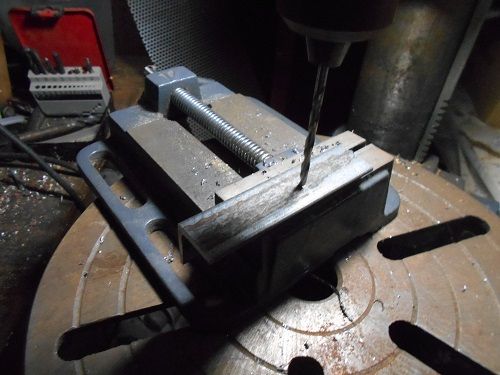 Tapping the 10-32 holes by hand. We discovered that dawn dish soap works even better than expensive tap oil. Don't believe me? Try it. Hubby freaked out and said it works better than tap magic. Just put a dab on the tip of the tap and you get a good, CLEAN hole. Pun intended.  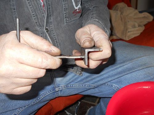 The two rear legs hold the frame together. 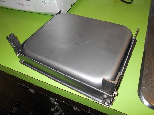 Here, the pan sits on three legs of the frame. So far, so good. All three legs are sitting squarely on the counter top.  What the front "pan stop" legs look like. EDIT: Should read "looked like". This feature has been eliminated from the final product 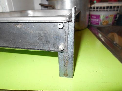 Hubby will be finishing the other front leg tomorrow then it will be time to fab the motor risers. We are going to order the motor in about two weeks. Then the diamond bit around the first of march. After we get the motor he is going to use a piece of thick sheet steel bent into a pivoting motor mount that will mount on the motor risers. Rather than making the pan look sloppy by cutting out spaces in it for the motor risers, he has decided to use a steel plate of the proper thickness as a spacer between the frame back piece and the motor risers. I gotta say, this thing is coming out pretty sweet so far. The only mistake was a broken tap which was popped right out with no problem by hitting it on the point with a steel hammer.. |
|
ziggy
spending too much on rocks
Member since June 2016
Posts: 483
|
Post by ziggy on Jan 16, 2017 19:13:38 GMT -5
After measuring the reality of things (ie. motor shaft length 3.25 inches,) hubby revised his motor mount to reflect that reality.  |
|
ziggy
spending too much on rocks
Member since June 2016
Posts: 483
|
Post by ziggy on Jan 17, 2017 17:38:06 GMT -5
The build progresses a little more. In the photo below he shows all four feet on the frame. 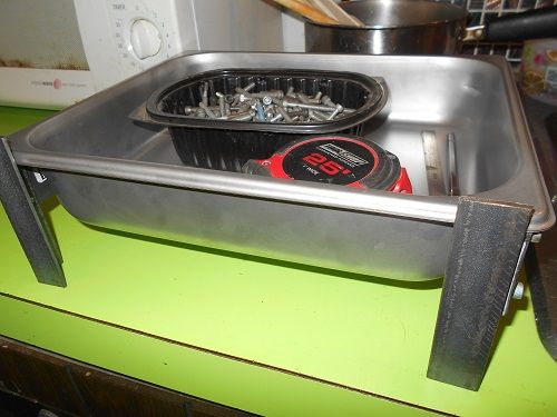 Next shot shows the spacer plates he installed so he wouldn't need to notch the pan for the motor risers. 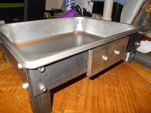 Last shot shows how the motor risers will be attached. They are held on by c-clamps for the photo. When done they will be held on by 1/4-20 socket head cap screws. 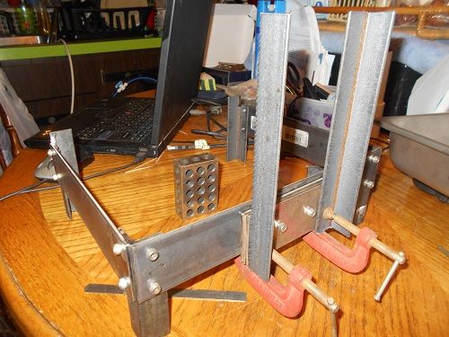 The only thing left he can do until we get the motor is actually drill and tap the riser bolt holes and screw them together. The risers were made extra long so if too much is there when we get the motor, they will simply be shortened then. Unfortunately, the mounting stud measurements aren't on the motor order page so hubby is going to wait until it comes to fabricate the actual motor mounting plate. |
|
ziggy
spending too much on rocks
Member since June 2016
Posts: 483
|
Post by ziggy on Jan 18, 2017 12:27:47 GMT -5
More work was completed today on the frame. He attached the motor risers with 1/4-20 x 3/4" socket head cap screws x 4. He drilled clearance holes in the risers themselves and used a 13/64 drill bit to tap for the screws through the now thick back plate on the frame. In the photo below hubby taps the 1/4-20 riser mounting holes while Max, our English Springer Spaniel, looks bored because hubby is busy doing something else other than playing with him.  The holes all line up. Yay If you have ever worked at drilling and tapping accurate holes by hand during fabrication, you know what is involved. It isn't always easy peasy. Enlarging clearance holes so a bolt will go into a tapped hole happens every day at every fab shop that does things by hand. Fortunately his holes all landed perfectly. 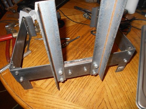 When everything is right in the hole department there is still the tiniest bit of wiggle before you tighten things up. Hubby uses a pair of 123 blocks to ensure everything is square when tightening. 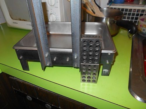 With the pan in it. The pan is a perfect fit. It HAS to be. Any movement in the pan while cutting the groove would allow variations in depth because the depth strip on the bottom of the pan would move as well. Not wanted. Tight non moving pan is a good thing. 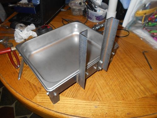 Speaking of pan movement, originally the front frame feet were designed as pan stops that stuck up over the edge of the pan to prevent it from wiggling. Hubby realized that they were poking him in the arms right where the arms would naturally rest to do the cutting. After closely examining the fit of the frame to the pan he determined that the tabs were not needed and cut those puppies right off. I guess he wasn't just guessing. It still doesn't move at all.  Well, that is really all he can do to it until we can afford the motor in about 2 weeks unless he decides to go out in the cold and do some powder coating out in the pole barn. Who knows....he might. |
|
ziggy
spending too much on rocks
Member since June 2016
Posts: 483
|
Post by ziggy on Jan 18, 2017 15:11:30 GMT -5
Well, I said he might go out and powder coat it and he did. Here it is before re-assembly  Re assembled:  With the pan installed side/rear view. Look at the reflection of the table and mouse cord. It's gloss black. 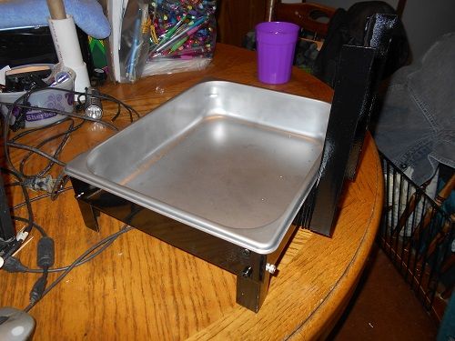 From the front  The powder coating came out pretty good and makes the frame look way nicer. It contrasts nicely with the stainless steel water pan. Now, all we have to do is wait about two weeks to buy this:  |
|
|
|
Post by 1dave on Jan 18, 2017 17:15:16 GMT -5
Thanks for sharing!
A picture is worth a thousand words is a true statement.
|
|
|
|
Post by captbob on Jan 18, 2017 19:30:24 GMT -5
May I please borrow your husband when you are done with him? He seems like a handy guy to have around!
|
|
ziggy
spending too much on rocks
Member since June 2016
Posts: 483
|
Post by ziggy on Jan 18, 2017 20:08:01 GMT -5
May I please borrow your husband when you are done with him? He seems like a handy guy to have around! You're the second person to ask that in this thread.  |
|
ziggy
spending too much on rocks
Member since June 2016
Posts: 483
|
Post by ziggy on Jan 18, 2017 21:28:16 GMT -5
Hubby's layout for the motor mounting plate he has to fab and bend.    Hole placement will be determined when we get the motor. |
|
ziggy
spending too much on rocks
Member since June 2016
Posts: 483
|
Post by ziggy on Jan 19, 2017 13:51:34 GMT -5
Hubby went and fabbed up the motor mounting plate as far as he could except the holes to mount it to the risers and the motor stud and shaft holes. First he measured and laid it out using a black sharpie and a six inch steel scale.  He went out to the pole barn with his angle grinder and cutting wheel and 3 Lb. sledge and came back in fifteen minutes later with this: ![]()   Below: It's a perfect fit on the motor risers. Not too shabby for a guy with a sledge, angle grinder and a bench vise. (He has a metal brake but it's buried in a bunch of our son in law's stuff out in the pole barn.)  He is going to drill motor mounting plate to riser holes next. |
|
ziggy
spending too much on rocks
Member since June 2016
Posts: 483
|
Post by ziggy on Jan 19, 2017 14:43:44 GMT -5
Clearance holes for the motor risers and the motor shaft hole have been drilled. All that is left in the fab department is four stud holes for the motor, four tapped holes in the motor risers and powder coat the motor mounting plate after all the holes get drilled.  The motor mounting plate held by C-clamps in the approximate position it will end up.  There were concerns from members of the forum when hubby first started designing this contraption about visibility of the cab while working on it and stuff like that. Below is the approximate view one will have when working with this setup. There will be no obstructions from what I can see. The bit will be right about where the light spot from the shaft hole is in the shadow on the bottom of the pan. Even if it was closer to the back of the pan than that, you could still clearly see your work. There is plenty of room for both hands to maneuver in the pan.  The bits should last way longer than if they were used on a Wizard. The entire grooving operation will be submerged. |
|
|
|
Post by 1dave on Jan 19, 2017 15:00:12 GMT -5
I thought about 4 disks glued to four sides of a square pan centered on groove cutting blade - 1/4, 1/8, 1/16, and 1/32 smaller than the diamond blade for quick change of groove depth.
|
|
ziggy
spending too much on rocks
Member since June 2016
Posts: 483
|
Post by ziggy on Jan 19, 2017 18:17:16 GMT -5
I thought about 4 disks glued to four sides of a square pan centered on groove cutting blade - 1/4, 1/8, 1/16, and 1/32 smaller than the diamond blade for quick change of groove depth. That is an awesome idea. We could only do two sides though because the pan is rectangular and only fits in one long side or the other. He's gonna stick with the depth stop strip in our case. Perhaps if someone else builds one they can capitalize on this idea better than us. He was originally thinking about a disk under the bit but had difficulty with how to keep it in place and he saw the infinitely adjustable depth strip as a more viable solution. He said he never thought about the gluing 4 of them down on 4 sides thing. He said if he would have thought of that he might have went with a square steam pan and done just that. A square pan in a rig like this would pull that trick off nicely though. Hubby is going to scribe a grid of positioning lines set at measured intervals into the pan bottom, which he can line the edge of the depth strip up with to make setting the depth strip easy. He will just use the depth strip as his straight edge to scribe the lines. He will make some pretty deep scribe lines then go ahead and cover the lines with black magic marker, the wipe the excess off lightly/carefully with acetone leaving nice black alignment lines in the bright stainless bottom. Another change/improvement in design involves the motor mounting plate where hubby has decided to make the lower holes for the locking bolts on the pivot section into slots instead of through holes. The slot will extend from the current hole to the edge of the plate so the mount can be pivoted up without fully removing the locking screws, but rather by simply loosening them. Explained in image below:  The motor mounting plate, having not previously mentioned anywhere is made of 16 gauge steel (1/16"thick.) Tomorrow's project: Make the depth stop strip. Hopefully out of stainless. |
|
ziggy
spending too much on rocks
Member since June 2016
Posts: 483
|
Post by ziggy on Jan 19, 2017 19:01:51 GMT -5
Having run out of things to do until the motor is ordered, hubby made up this parts/tools list. 2" x 1/8" x 9 11/16" Steel plate x 2 (frame side plates) All Steel From Home Depot 2" x 1/8" x 12" Steel plate x 1 (frame back plate) 2" x 1/8" x 4 1/2" Steel plate x 3 (can substitute 2" x 3/8" x 4 1/2" Steel plate x 1) Spacer(s) 1" x 1" x 4" Angle steel x 4 (rear/front leg/corner connectors) 1" x 1" x 8" Angle steel x 2 (motor risers) 4 5/8" x 12 5/8" x 16 gauge piece of sheet steel for the motor mounting plate x 1 1" x 10" x 16 gauge sheet metal (powder coated) or equivalent stainless for cutting depth gauge x 1 3" C-clamp x 2 for holding depth strip to bottom of pan 10-32 flat washer x 4 for motor mounting plate locking/pivot bolts 10-32 locking washer x 4 for motor mounting plate locking/pivot bolts 10-32 x 1/4" socket head cap screw x 16 for frame bolts and motor mounting plate locking/pivot bolts 10-32 x 1/2" socket head cap screw x 2 for holding spacer plate to frame back plate 1/4-20 x 3/4" socket head cap screw x 4 for holding motor risers to the spacer plate Kitchen Essentials Steam Table Pan re-order # 366810 (Purchase at GFS) x 1Century 9721 3.3 motor 115/208-230 Volt 1550 RPM globalindustrial.com x 1 Twofers Jewelry bits x 1 (comes two in a package) Ebay vendorAC power cord 6' long at least x 1 Home Depot Flex conduit to cover box to motor wire (2 feet x 1) Home Depot Electrical junction box x 1 Home Depot On/off electrical switch x 1 Home Depot On/off light switch and switch plate x 1 Tools required: Drill bit set Drill press 4 1/2"angle grinder/w metal cutting blades Metal cutoff saw Center punch Hammers (center punch brass, 3 Lb. sledge for bending steel) Large bench vise Measuring scale (ruler) Metal scribe (carbide tip) Sharpie marker Hex wrenches Great to have extra: Powder coater Arbor press (straightening out curve from bending, in the flat, in the motor plate) Metal bending brake and knowledge to bend to size exactly Belt grinder (cleaning up edges, etc.) Hubby's main tips. CENTER PUNCH HOLES AND ONLY USE A DRILL PRESS. Frame side plates at front upper corners where plate meets pan were radiused to fit in curve of pan lip with belt grinder ensuring complete contact of pan to frame top edge. Detail photo below:  |
|
|
|
Post by 1dave on Jan 20, 2017 9:25:04 GMT -5
I have never grooved.
On further consideration 1/4" is probably too deep and 1/32" too shallow.
Probably 1/6", 1/8", 1/10" and 1/12" would be better groove depths.
Any comments from actual groovers? |
|
ziggy
spending too much on rocks
Member since June 2016
Posts: 483
|
Post by ziggy on Jan 20, 2017 10:18:46 GMT -5
I have never grooved.
On further consideration 1/4" is probably too deep and 1/32" too shallow.
Probably 1/6", 1/8", 1/10" and 1/12" would be better groove depths.
Any comments from actual groovers? I personally am going to set my first cut depth to 20 gauge square wire. Why there is a need for different depths of cut I am not really sure. I like when the wire is just set even with the surface of the cab and don't really plan on making much deeper cuts ever. Hubby just sees the ability to set different depths as sort of an added bonus feature that will rarely be used. After we get the motor and the bit we will use a length of 20 gauge square wire laying next to the depth gauge and even with the edge of the bit. The we will clamp the depth strip in place. Remove the wire and its set to 20 gauge cutting depth. If I decide to use another wire size down the road, just repeat depth setting procedure. Here is a couple of pics showing the depth stop strip hubby came up with. It is simply a 1" wide strip of really stiff 1/16" thick 7075 aluminum clamped to the pan by two C-clamps (to be replaced with new ones soon.) I think the real advantage of the stop strip is that one won't need to guess if the groove is evenly cut and one could probably do the groove without even looking.   |
|