adrian65
Cave Dweller  Arch to golden memories and to great friends.
Member since February 2007
Posts: 10,778
|
Post by adrian65 on Jul 25, 2008 11:01:56 GMT -5
Hi, everyone! Would you please help me? I'm working right now at a design for a steel structure (building). It will be manufactured abroad so I have to entitle all the drawings in English. I have to give some drawings of the pieces that will be cut, like in the pic below: 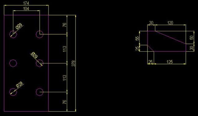 How should I entitle such drawings? In Romanian we name them "cutting" because they are used to cut the pieces at the specified dimensions. Thank you very much, Adrian |
|
|
|
Post by akansan on Jul 25, 2008 11:12:56 GMT -5
Would you call it a draft, possibly? People that produce that kind of work here are called draftsmen, so it would make sense that the result would be a draft...
|
|
grayfingers
Cave Dweller
Member since November 2007
Posts: 4,575 
|
Post by grayfingers on Jul 25, 2008 11:57:44 GMT -5
Hopefully someone with direct knowledge of this will respond, but my thought is that if the drawing is the same size as the parts will be it would be a template.
If not, the description 'cutting diagram' might do the trick.
I've pasted this from the web....
The term diagram
Diagram has two meanings in common sense.[1]
1. A collective term for any visual information device, like the term "illustration" often used as a representative term, to stand for the whole class of technical genres, including graphs and tables.
2. The specific class of visual display, that show qualitative data with shapes that are connected by lines, arrows, or other visual links.
The term diagram is used in both meanings in science. For example Michael Anderson (1997) stated "diagrams are pictorial, yet abstract, representations of information, and maps, line graphs, bar charts, engineering blueprints, and architects' sketches are all examples of diagrams, whereas photographs and video are not".
|
|
|
|
Post by Tweetiepy on Jul 25, 2008 12:47:42 GMT -5
How about technical drawings.
Or blue prints
|
|
|
|
Post by Titania on Jul 25, 2008 12:57:58 GMT -5
I'm an engineer, Adrian.  Here, we call drawings like those "Engineering Drawings". |
|
Tigger
freely admits to licking rocks
 The Wonderful Thing About Tiggers is I'm the Only One!
Member since January 2008
Posts: 896
|
Post by Tigger on Jul 25, 2008 14:27:21 GMT -5
Adrian, My son is currently studing architecture and drafting. He said this type of drawing would be a mechanical drawing. Hope it helps.
Tonja
|
|
|
|
Post by parfive on Jul 25, 2008 14:32:01 GMT -5
Adrian - Basically, all the drawings for a building would amount to a set of "plans".
A drawing looking down from above, such as the layout of the first floor, or the roof, or the foundation, or whatever, is a "plan" view.
A drawing showing the front (or side or rear) of the building, or looking at a wall (such as a cabinet layout) is an "elevation" view.
A drawing looking at a particular place in the structure, as if it had been cut open, is a "section".
And drawings of specific pieces (like the two parts you show) or areas would be "details".
Let's say the one on the left (a gusset plate or splice plate?) is part A and the other is part B. If you can see part A on the first floor plan, for example, then label it "part A" and note "see detA1"
Or you could just label all the parts that show on the plan views and elevations and list them all in a "parts list" or "bill of materials"
The parts list (or BOM) should be a chart (another drawing) listing the part number, part name, quantity, type of material, length, width, thickness, etc. Don't forget stuff like bolts, nuts and washers if they're gonna be supplied by the same place that fabricates the building.
And then there would be "detail" dwgs showing all the info needed to actually make a piece. Some complicated pieces might even need three detail dwgs - plan, front and side views, to convey all the necessary info.
A couple of suggestions:
Don't forget to label all your dimensions, such as mm or cm.
You've got some unusual dimensions on your two details . . . keep it as simple as possible . Much easier (and cheaper) for someone to make, and someone else (you?) to put together.
Rich
|
|
|
|
Post by Titania on Jul 25, 2008 15:00:55 GMT -5
Adrian - Basically, all the drawings for a building would amount to a set of "plans". A drawing looking down from above, such as the layout of the first floor, or the roof, or the foundation, or whatever, is a "plan" view. A drawing showing the front (or side or rear) of the building, or looking at a wall (such as a cabinet layout) is an "elevation" view. A drawing looking at a particular place in the structure, as if it had been cut open, is a "section". And drawings of specific pieces (like the two parts you show) or areas would be "details". Let's say the one on the left (a gusset plate or splice plate?) is part A and the other is part B. If you can see part A on the first floor plan, for example, then label it "part A" and note "see detA1" Or you could just label all the parts that show on the plan views and elevations and list them all in a "parts list" or "bill of materials" The parts list (or BOM) should be a chart (another drawing) listing the part number, part name, quantity, type of material, length, width, thickness, etc. Don't forget stuff like bolts, nuts and washers if they're gonna be supplied by the same place that fabricates the building. And then there would be "detail" dwgs showing all the info needed to actually make a piece. Some complicated pieces might even need three detail dwgs - plan, front and side views, to convey all the necessary info. A couple of suggestions: Don't forget to label all your dimensions, such as mm or cm. You've got some unusual dimensions on your two details . . . keep it as simple as possible . Much easier (and cheaper) for someone to make, and someone else (you?) to put together. Rich This isn't a plan for an assembly, though. This is the single drawing that a machine shop would use to make a part. |
|
|
|
Post by parfive on Jul 25, 2008 15:47:07 GMT -5
Whatever. Adrian's words: " . . . a design for a steel structure (building). It will be manufactured abroad so I have to entitle all the drawings in English."
Chances are, one steel fabrication outfit will make all the pieces for this building. Not typically thought of as "machine shop" work.
Rich
|
|
|
|
Post by cpdad on Jul 25, 2008 17:27:07 GMT -5
adrian...if you were going to send that cutting to me....is the cutting above considered a finished cutting?....if it is...there is not enough info on it to be made.
to answer your question about what to call it...here in the united states what you provided above would be considered a {drawing}.
if any of your drawings show any part of the building assembled....then they would be referred to as plans....then many details and sections would need to be applied as rich described above.
just talking my preference now on how i would like to recieve them.
i would like 1 drawing of the part on the left.....1 of the part on the right.....it should have a title block in the right hand corner of the drawing....1 drawing labeled in the title block...1 of 96.....second drawing...2 of 96.....96 is just an example of how many drawings.
or in the title block.....1 and 2 of 96 if both are provided on 1 drawing as above and under each part ...part 1....under second part....part 2.
i have a couple of examples of drawings with title blocks i could email you if you pm me your email....kev.
|
|
|
|
Post by parfive on Jul 25, 2008 21:54:16 GMT -5
|
|
adrian65
Cave Dweller
Arch to golden memories and to great friends.
Member since February 2007
Posts: 10,778
|
Post by adrian65 on Jul 25, 2008 22:52:10 GMT -5
Thanks folks!
Rich and Kev, The design contains:
- plans of the whole elements (columns, beams and so on) viewed from different angles;
- details, such as the base of the column, the end of the beam, (where more pieces are welded together and bigger scale is needed to view and dimension them)
- those drawings, that are just for cutting the steel pieces that will be welded together to form the ellements.
With so many opinions, I think I will simply name that sort of drawings with the code of the piece that it describes: "P 01" for example.
Thank you everyone
Adrian
|
|
|
|
Post by krazydiamond on Jul 27, 2008 8:52:26 GMT -5
i think Parfive pretty much described it the best. i would call what Adrian has shown as "plan details". although in what he has shown tolerances would have to be expressed and possibly quantities required or specified in another larger assembly drawing. additionally, most metal building manufacturers will generate their own set of fabrication details (also known as shop drawings) that would be reviewed by the engineer/customer for approval before actual parts are made and welded for construction. i'm curious now, what'cha building, Adrian?  KD |
|
adrian65
Cave Dweller
Arch to golden memories and to great friends.
Member since February 2007
Posts: 10,778
|
Post by adrian65 on Aug 1, 2008 7:57:14 GMT -5
Thanks for the replies. Those drawings are in addition to all the plan and details and picture one piece only. The thickness is given above the drawing (for example the sub-title for one in the left side is 15 x 174 - 378). The finish... well what can I say? In stel structures there are no special requirements for the finish. The coating requirements are speciffied in the written notes and anyway they will be applied only after the asembly of the pieces into ellements (columns, beams and so on). In the end, I addopted a simple solution: I named those drawings with the name of the piece, for example: P15 15 x 174 - 378 Thanks again, Adrian PS. KD, this is a ground floor storage hall, nothing spectacular. Thanks for the interest |
|


 Have a quartzy day