ziggy
spending too much on rocks

Member since June 2016
Posts: 483 
|
Post by ziggy on Jan 19, 2017 22:01:59 GMT -5
Do you consider the back support to be the source of your success? Presumably that prevents blowouts just as would happen with splintering on drilling wood. I'm not totally sure to be honest but I have worked wood since child hood and recently cut acrylic for homemade saw hoods and have used this method in all 3 ventures and never had any problems with any of them. An it seems several people do. I also go extremely slow letting the cutting agent do all the work without force. All my drilled rocks look great......on one side  . |
|
ziggy
spending too much on rocks
Member since June 2016
Posts: 483
|
Post by ziggy on Jan 19, 2017 19:01:51 GMT -5
Having run out of things to do until the motor is ordered, hubby made up this parts/tools list. 2" x 1/8" x 9 11/16" Steel plate x 2 (frame side plates) All Steel From Home Depot 2" x 1/8" x 12" Steel plate x 1 (frame back plate) 2" x 1/8" x 4 1/2" Steel plate x 3 (can substitute 2" x 3/8" x 4 1/2" Steel plate x 1) Spacer(s) 1" x 1" x 4" Angle steel x 4 (rear/front leg/corner connectors) 1" x 1" x 8" Angle steel x 2 (motor risers) 4 5/8" x 12 5/8" x 16 gauge piece of sheet steel for the motor mounting plate x 1 1" x 10" x 16 gauge sheet metal (powder coated) or equivalent stainless for cutting depth gauge x 1 3" C-clamp x 2 for holding depth strip to bottom of pan 10-32 flat washer x 4 for motor mounting plate locking/pivot bolts 10-32 locking washer x 4 for motor mounting plate locking/pivot bolts 10-32 x 1/4" socket head cap screw x 16 for frame bolts and motor mounting plate locking/pivot bolts 10-32 x 1/2" socket head cap screw x 2 for holding spacer plate to frame back plate 1/4-20 x 3/4" socket head cap screw x 4 for holding motor risers to the spacer plate Kitchen Essentials Steam Table Pan re-order # 366810 (Purchase at GFS) x 1Century 9721 3.3 motor 115/208-230 Volt 1550 RPM globalindustrial.com x 1 Twofers Jewelry bits x 1 (comes two in a package) Ebay vendorAC power cord 6' long at least x 1 Home Depot Flex conduit to cover box to motor wire (2 feet x 1) Home Depot Electrical junction box x 1 Home Depot On/off electrical switch x 1 Home Depot On/off light switch and switch plate x 1 Tools required: Drill bit set Drill press 4 1/2"angle grinder/w metal cutting blades Metal cutoff saw Center punch Hammers (center punch brass, 3 Lb. sledge for bending steel) Large bench vise Measuring scale (ruler) Metal scribe (carbide tip) Sharpie marker Hex wrenches Great to have extra: Powder coater Arbor press (straightening out curve from bending, in the flat, in the motor plate) Metal bending brake and knowledge to bend to size exactly Belt grinder (cleaning up edges, etc.) Hubby's main tips. CENTER PUNCH HOLES AND ONLY USE A DRILL PRESS. Frame side plates at front upper corners where plate meets pan were radiused to fit in curve of pan lip with belt grinder ensuring complete contact of pan to frame top edge. Detail photo below:  |
|
ziggy
spending too much on rocks
Member since June 2016
Posts: 483
|
Post by ziggy on Jan 19, 2017 18:17:16 GMT -5
I thought about 4 disks glued to four sides of a square pan centered on groove cutting blade - 1/4, 1/8, 1/16, and 1/32 smaller than the diamond blade for quick change of groove depth. That is an awesome idea. We could only do two sides though because the pan is rectangular and only fits in one long side or the other. He's gonna stick with the depth stop strip in our case. Perhaps if someone else builds one they can capitalize on this idea better than us. He was originally thinking about a disk under the bit but had difficulty with how to keep it in place and he saw the infinitely adjustable depth strip as a more viable solution. He said he never thought about the gluing 4 of them down on 4 sides thing. He said if he would have thought of that he might have went with a square steam pan and done just that. A square pan in a rig like this would pull that trick off nicely though. Hubby is going to scribe a grid of positioning lines set at measured intervals into the pan bottom, which he can line the edge of the depth strip up with to make setting the depth strip easy. He will just use the depth strip as his straight edge to scribe the lines. He will make some pretty deep scribe lines then go ahead and cover the lines with black magic marker, the wipe the excess off lightly/carefully with acetone leaving nice black alignment lines in the bright stainless bottom. Another change/improvement in design involves the motor mounting plate where hubby has decided to make the lower holes for the locking bolts on the pivot section into slots instead of through holes. The slot will extend from the current hole to the edge of the plate so the mount can be pivoted up without fully removing the locking screws, but rather by simply loosening them. Explained in image below:  The motor mounting plate, having not previously mentioned anywhere is made of 16 gauge steel (1/16"thick.) Tomorrow's project: Make the depth stop strip. Hopefully out of stainless. |
|
ziggy
spending too much on rocks
Member since June 2016
Posts: 483
|
Post by ziggy on Jan 19, 2017 14:43:44 GMT -5
Clearance holes for the motor risers and the motor shaft hole have been drilled. All that is left in the fab department is four stud holes for the motor, four tapped holes in the motor risers and powder coat the motor mounting plate after all the holes get drilled.  The motor mounting plate held by C-clamps in the approximate position it will end up.  There were concerns from members of the forum when hubby first started designing this contraption about visibility of the cab while working on it and stuff like that. Below is the approximate view one will have when working with this setup. There will be no obstructions from what I can see. The bit will be right about where the light spot from the shaft hole is in the shadow on the bottom of the pan. Even if it was closer to the back of the pan than that, you could still clearly see your work. There is plenty of room for both hands to maneuver in the pan.  The bits should last way longer than if they were used on a Wizard. The entire grooving operation will be submerged. |
|
ziggy
spending too much on rocks
Member since June 2016
Posts: 483
|
Post by ziggy on Jan 19, 2017 13:51:34 GMT -5
Hubby went and fabbed up the motor mounting plate as far as he could except the holes to mount it to the risers and the motor stud and shaft holes. First he measured and laid it out using a black sharpie and a six inch steel scale.  He went out to the pole barn with his angle grinder and cutting wheel and 3 Lb. sledge and came back in fifteen minutes later with this: ![]()   Below: It's a perfect fit on the motor risers. Not too shabby for a guy with a sledge, angle grinder and a bench vise. (He has a metal brake but it's buried in a bunch of our son in law's stuff out in the pole barn.)  He is going to drill motor mounting plate to riser holes next. |
|
ziggy
spending too much on rocks
Member since June 2016
Posts: 483
|
Post by ziggy on Jan 19, 2017 10:16:37 GMT -5
Well, the funny thing is they do have a square bit for wood. Rocks are a different story. For metal they brooch hole. (Spelling) Broaching or broach is the proper spelling. The can make a broach to make just about any shape of hole. The broaching process involves vertical thrust of a broaching tool through the piece being broached. Hubby used to do that sometimes on a hand arbor press. Love all the creative possibilities for jugglerguy to pick from. Interesting ideas. |
|
ziggy
spending too much on rocks
Member since June 2016
Posts: 483
|
Post by ziggy on Jan 18, 2017 21:28:16 GMT -5
Hubby's layout for the motor mounting plate he has to fab and bend.    Hole placement will be determined when we get the motor. |
|
ziggy
spending too much on rocks
Member since June 2016
Posts: 483
|
Post by ziggy on Jan 18, 2017 20:08:01 GMT -5
May I please borrow your husband when you are done with him? He seems like a handy guy to have around! You're the second person to ask that in this thread.  |
|
ziggy
spending too much on rocks
Member since June 2016
Posts: 483
|
Post by ziggy on Jan 18, 2017 15:11:30 GMT -5
Well, I said he might go out and powder coat it and he did. Here it is before re-assembly  Re assembled:  With the pan installed side/rear view. Look at the reflection of the table and mouse cord. It's gloss black. 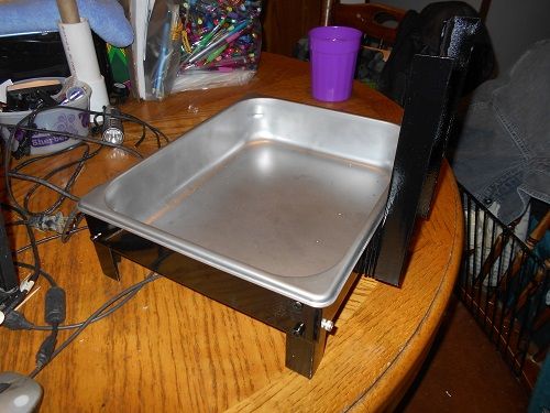 From the front  The powder coating came out pretty good and makes the frame look way nicer. It contrasts nicely with the stainless steel water pan. Now, all we have to do is wait about two weeks to buy this:  |
|
ziggy
spending too much on rocks
Member since June 2016
Posts: 483
|
Post by ziggy on Jan 18, 2017 12:27:47 GMT -5
More work was completed today on the frame. He attached the motor risers with 1/4-20 x 3/4" socket head cap screws x 4. He drilled clearance holes in the risers themselves and used a 13/64 drill bit to tap for the screws through the now thick back plate on the frame. In the photo below hubby taps the 1/4-20 riser mounting holes while Max, our English Springer Spaniel, looks bored because hubby is busy doing something else other than playing with him.  The holes all line up. Yay  If you have ever worked at drilling and tapping accurate holes by hand during fabrication, you know what is involved. It isn't always easy peasy. Enlarging clearance holes so a bolt will go into a tapped hole happens every day at every fab shop that does things by hand. Fortunately his holes all landed perfectly. 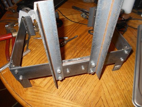 When everything is right in the hole department there is still the tiniest bit of wiggle before you tighten things up. Hubby uses a pair of 123 blocks to ensure everything is square when tightening. 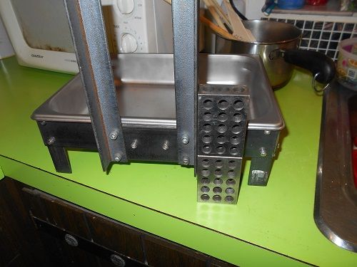 With the pan in it. The pan is a perfect fit. It HAS to be. Any movement in the pan while cutting the groove would allow variations in depth because the depth strip on the bottom of the pan would move as well. Not wanted. Tight non moving pan is a good thing. 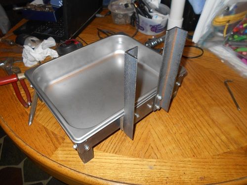 Speaking of pan movement, originally the front frame feet were designed as pan stops that stuck up over the edge of the pan to prevent it from wiggling. Hubby realized that they were poking him in the arms right where the arms would naturally rest to do the cutting. After closely examining the fit of the frame to the pan he determined that the tabs were not needed and cut those puppies right off. I guess he wasn't just guessing. It still doesn't move at all.  Well, that is really all he can do to it until we can afford the motor in about 2 weeks unless he decides to go out in the cold and do some powder coating out in the pole barn. Who knows....he might. |
|
ziggy
spending too much on rocks
Member since June 2016
Posts: 483
|
Post by ziggy on Jan 17, 2017 18:49:48 GMT -5
Are you thinking like giving the stone a muffin top? (sorry for the visual). That is hilarious |
|
ziggy
spending too much on rocks
Member since June 2016
Posts: 483
|
Post by ziggy on Jan 17, 2017 18:43:18 GMT -5
Hi Tiger Personally from painful and not entirely successful experience, I'm not a fan of drilling. Me either. The blowout craters on the bottom side seem to happen even when I'm super careful. It might be due to the fact that most of the stones I am drilling are no more than mohs 3 in hardness (Michigan septarian nodules and Petoskey stones.) Because of this I have decided to (for the most part) no longer drill holes and instead do some groove wrapping. Hubby is building a groove router right now just for that. |
|
ziggy
spending too much on rocks
Member since June 2016
Posts: 483
|
Post by ziggy on Jan 17, 2017 17:38:06 GMT -5
The build progresses a little more. In the photo below he shows all four feet on the frame. 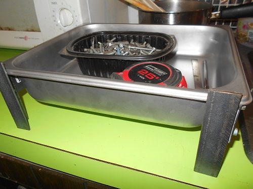 Next shot shows the spacer plates he installed so he wouldn't need to notch the pan for the motor risers. 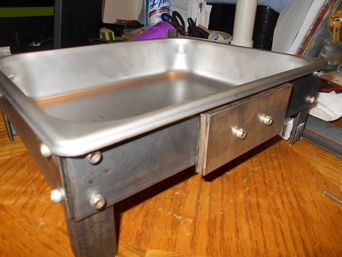 Last shot shows how the motor risers will be attached. They are held on by c-clamps for the photo. When done they will be held on by 1/4-20 socket head cap screws. 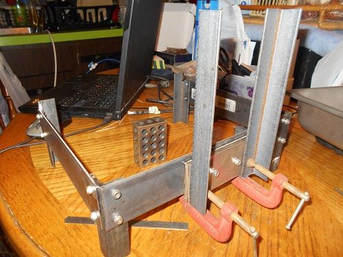 The only thing left he can do until we get the motor is actually drill and tap the riser bolt holes and screw them together. The risers were made extra long so if too much is there when we get the motor, they will simply be shortened then. Unfortunately, the mounting stud measurements aren't on the motor order page so hubby is going to wait until it comes to fabricate the actual motor mounting plate. |
|
ziggy
spending too much on rocks
Member since June 2016
Posts: 483
|
Post by ziggy on Jan 17, 2017 10:46:45 GMT -5
Now a couple hundred bucks spread over a few months is probably do-able. Thanks for the idea. That's how we afford our expensive hobby too. Build whenever you can. Cuts literally thousands of dollars off the cost of equipment. Every piece of equipment we own was either an ancient piece gotten for free and we modified or fixed, or one we built from scratch. I mean $1999.00 for a cab machine?  Really? NOT! |
|
ziggy
spending too much on rocks
Member since June 2016
Posts: 483
|
Post by ziggy on Jan 17, 2017 10:20:35 GMT -5
Just out of curiosity, I got out my Kill A Watt meter the other day to see how much electricity my new rock saw is using. When it's cutting, it draws about 200 watts (give or take). Cutting a slab off a 3.5" thunderegg took about .05 KWH, or about .04 cents worth of electricity. I don't think that's going to break the bank anytime soon. You might want to keep those pillow blocks greased up. They are exposed to the grit in the oil. I hate to criticize because it is a fantastic build, but those pillow blocks probably should have been mounted outside the tub. There would have been more drop in the clamp also. Looks like you could have gotten another couple inches if the bearing wasn't under the clamp. At the very least you should put a cover over them. The less dirt that has the possibility of contaminating the bearing grease the better. Covers are a good alternative to a complete re-design. Other than that, awesome saw. |
|
ziggy
spending too much on rocks
Member since June 2016
Posts: 483
|
Post by ziggy on Jan 17, 2017 9:35:45 GMT -5
watch how much info you give out.........the forum is for sale That map isn't hosted by RTH so the site being for sale shouldn't be an issue. What you say holds true for any forum...even ones not for sale. |
|
ziggy
spending too much on rocks
Member since June 2016
Posts: 483
|
Post by ziggy on Jan 17, 2017 6:49:00 GMT -5
I would be much more concerned about rock grit getting in the sliding ways of a machine designed for cutting metal, than if it rusts. Likely machines used for cutting granite by milling are purpose built. Any cutting fluid would need to be carefully filtered, or better yet, not recycled in the machine. I've seen floor dry [kitty litter] raise havoc with sliding ways and coolant filters on CNC machines. Like most things in life, there is a really simple workaround solution for the dilemma of water and mills. The answer is: Put the stone in a plastic container filled with water.......Wow....who would have thought of that. Clamp the entire assembly down. I'm not going to waste my time explaining this anymore so just go to this link and read all about it (the page is written in three steps (pages) and the answer is not on the first step.) BTW, the author of this article actually uses a CNC milling router and not a bridgeport. I think you could swing this simple slot on a bridgeport though. A good machinist (like my hubby) would have no issues at all.
Since I have never personally used a milling machine to put a slot on a rock, I could only guess how they cooled the bit without wasting the table and ways. Well, that is why there is google. I googled "milling in rock" and voila, just like that I had the answer to the coolant question. Google is your friend. I did know, before I opened my mouth to answer juddlerguys question however, that milling machines are being used for stuff like that.OH yeah, the bits used are like sintered diamond tool steel rods, much like the bottom picture that i posted. With something like a milling machine in your arsenal, you would be stupid to try and do it any other way.They also make (really costly) purpose built CNC stone routers,  where the stone is clamped down to a table and the milling/routing head moves instead of the table. It is on fancy machines like these that the fancy diamond bits with built in coolant holes are used. where the stone is clamped down to a table and the milling/routing head moves instead of the table. It is on fancy machines like these that the fancy diamond bits with built in coolant holes are used.
The one pictured above looks like it might use flat linear motors for all the x and z axis moves (also known as Mag Drives.) Please, don't ask me to explain what that is....(although I could because hubby used to install them almost everyday.) That might also be a simple rack driven x/z axis but he can't really tell from the photo. He says the small steel rail next to the main linear bearing rail looks like what might be a rack and the one up top on the moving bridge also looks like a gear drive rack.These are basically the same kind of machines that my hubby used to design and build for a company called Glassline Corp. but the ones he made were used for cutting/edging glass, not rocks (working with glass requires tools with machining done to extremely small tolerances, capable of working with one of the more brittle and shatter prone substances that are worked this way.)Go one step beyond the simple CNC mill/router and you have the multiple axis stone cutting mill/router. It can carve statues and busts for crying out loud.I don't think the Petoskey slot was done on one of those. That would be overkill for a simple 3" long slot. But it could have been. Oh, and the coolant on this machine??? Looks like simple H2O. Probably not. The water presents a rust issue inside the mill and the stuff being used is most likely filtered and recirculated. Based on all the facts, I would say that the most likely way that slot was put in that Petoskey was with a regular mill with a diamond bit with the rock submerged in a tank of water. I chose the regular mill based on the fact that Petoskey stones are not a mass manufactured kind of thing. It was likely done as a one off or maybe he does them more than that. Petoskeys don't come made to order so the chances of having enough stones of that size to make a bunch of them are slim to few. Probably a product likely made by a lone lapidary probably somewhere in Michigan using a re-purposed vertical mill using diamond bits with the rock in a tank is the most plausible answer. How could it plausibly be done with no mill? Once again, first submerge the piece in a plastic tub filled with water Very carefully drill a series of adjacent holes to the exact same depth as close together as possible. Break or saw the space between the holes. Use large diamond drill bits or a diamond oscillating blade and smooth down the ridges in the hole until it looks like a smooth slot (which would take a long time I think.) A mill would be way easier. |
|
ziggy
spending too much on rocks
Member since June 2016
Posts: 483
|
Post by ziggy on Jan 16, 2017 22:14:59 GMT -5
If you do it using a milling machine everything must be protected from the water used. Rust will kill the machine. A dremel tool works for me and have the water drip into a 5 gallon bucket. Take your time and use a diamond coated saw blade. Use water or it will not last long. What do you do to get the core out and leave a smooth bottom without danger of cracking the stone? Stone rarely, if ever does exactly what you want with leverage. To remove the core you would need to break something somewhere. I can almost guarantee that particular petoskey stone was not slotted the way that you suggest. That is a milled slot if I've ever seen one. Just use mill cutting fluid. The most mills can recycle their coolant. That's what they use for steel. Its made for them. Won't rust. If you look closely at the bits in the top picture I posted, you can see holes and slots in the cutting area of the bit and a large hole in the end to let coolant flow through when cutting rock. The slurry from the process is forced out through the slots in the bit by the pressure of the coolant flow. Notice there is even a hole in the end for when it is doing the initial plunge into the slot and the groove in it supplies coolant to the outside edge of the bottom of the bit. That is where the most wear and tear would occur with no coolant. Besides, I've already provided proof that milling machines are used to do this in my pictures of sintered diamond end mills designed to mill granite. If the slot has a smooth bottom, it was milled. |
|
ziggy
spending too much on rocks
Member since June 2016
Posts: 483
|
Post by ziggy on Jan 16, 2017 21:45:48 GMT -5
Water-jet? Laser? The ends look rounded to me....but my eyesight is as old as I am! Yes, the ends are rounded. I could drill the ends. I don't know how to do the straight parts in-between. A Bridgeport mill could probably do that. (with the right end mill bit) Hubby made holes in steel that way. They're called slots. The piece is clamped to a moving table that moves under a massive drill. The drill uses special bits called end mills. The bits are held in the mill by something called collets. Wouldn't be too hard to do on that Petoskey with one of those. I imagine they used a diamond bit. Probably something similar to this:  Or one of these. Advertised as a diamond end mill bit:  ![]() If it can mill granite, Petoskey is a piece of cake. You can buy a nice used Bridgeport mill for probably anywhere from around $3,500 to $5,000. They only weigh about 1500 lbs. ![]() |
|
ziggy
spending too much on rocks
Member since June 2016
Posts: 483
|
Post by ziggy on Jan 16, 2017 19:13:38 GMT -5
After measuring the reality of things (ie. motor shaft length 3.25 inches,) hubby revised his motor mount to reflect that reality.  |
|


 .
. 


 If you have ever worked at drilling and tapping accurate holes by hand during fabrication, you know what is involved. It isn't always easy peasy. Enlarging clearance holes so a bolt will go into a tapped hole happens every day at every fab shop that does things by hand. Fortunately his holes all landed perfectly.


 Really?


